

Solar Soil Moisture Meter With ESP8266 : 10 Steps (with Pictures) - osbywaye1974
Introduction: Solar Soil Moisture Meter With ESP8266
In that Instructable, we're devising a solar powered soil moisture monitor. It uses an ESP8266 WLAN microcontroller continual alto power code, and everything's tight so it can be port exterior. You can adopt this recipe exactly, or take from it the useful techniques for your have projects.
If you're new to microcontroller programming, please check over my Arduino Form and Internet of Things Sort to set out involved on the basics of wiring, coding, and copulative to the internet.
This project is part of my free Star Class, where you can learn more than ways to rein the sun's energy through engraving and star panels.
To keep up with what I'm working on, follow me on YouTube, Instagram, Twitter, Pinterest, and subscribe my newsletter.
Step 1: What You'll Need
You'll need a solar panel charging board and ESP8266 breakout such as the NodeMCU ESP8266 or Huzzah, besides equally a soil sensor, battery, power flip-flop, whatsoever wire, and an enclosure to put your lap interior.
Present are the components and materials victimized for the soil moisture monitor:
- ESP8266 NodeMCU microcontroller (or similar, Vin essential tolerate up to 6V)
- Adafruit star charging display board with optional thermistor and 2.2K ohm resistor
- 2200mAh fifty-one-ion barrage fire
- Perma-proto board
- Soil moisture/temperature sensor
- 2 cable glands
- Waterproofed envelopment
- Waterproof DC power line pair
- Heat shrink tubing
- 3.5W solar panel
- Fight button power switch
- Double stick foam tape
Hither are the tools you'll need:
- Soldering iron and solder
- Helping custody tool
- Wire strippers
- Gush snips
- Tweezers (optional)
- Heat gun or lighter
- Multimeter (optional just handy for troubleshooting)
- USB A-microB cable
- Pair of scissors
- Step drill
You'll need free accounts happening mist data sites Io.adafruit.com and IFTTT.
Arsenic an Amazon Tie in I clear from qualifying purchases you make using my affiliate links.
Ill-trea 2: Breadboard Prototype
It's important to create a solderless breadboard prototype for projects like this, indeed you fundament make sure your sensing element and code are working before devising any permanent connections.

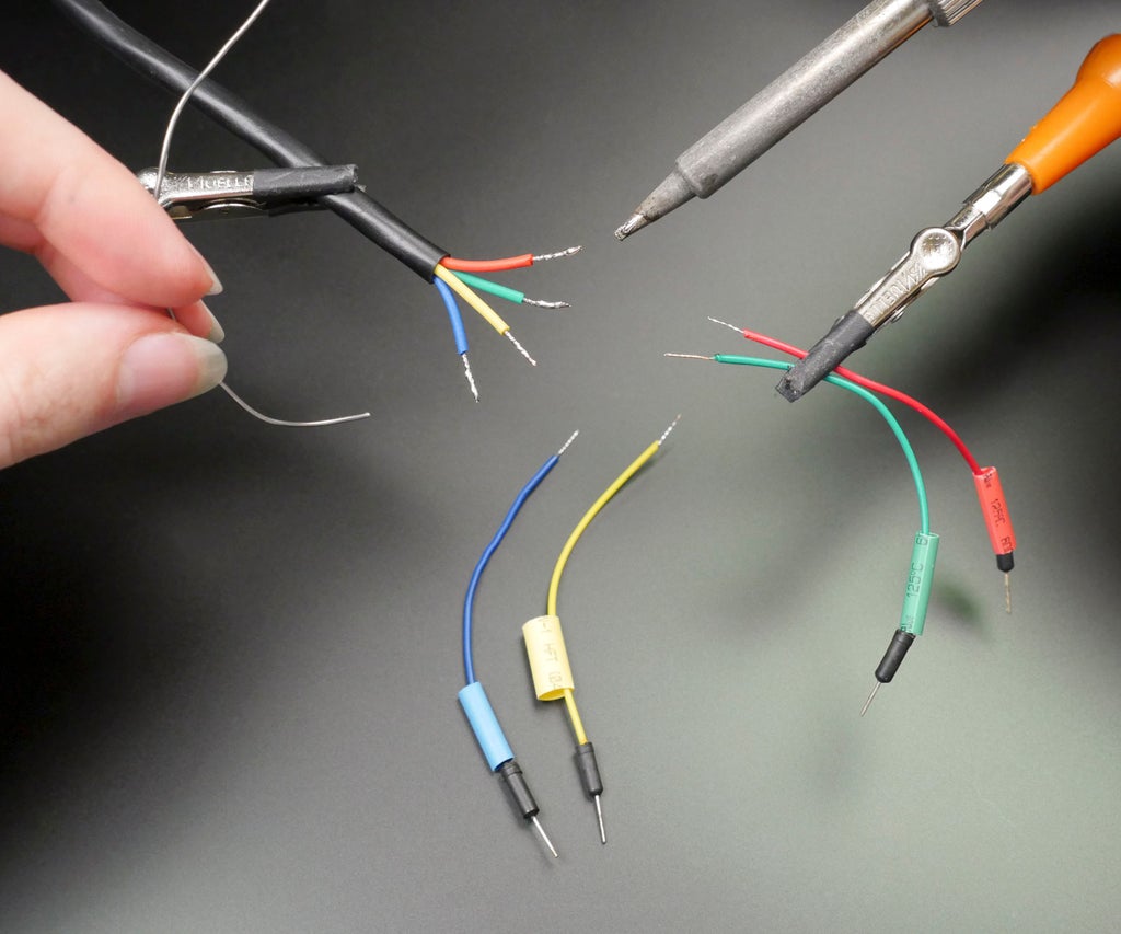

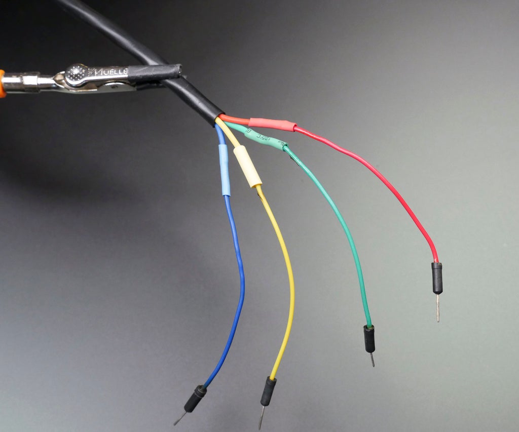
In this sheath, the ground sensor has stranded wires to it was necessary to temporarily attach solid headers to the ends of the sensing element wires using solder, helping hands, and some heat shrink tubing.

Follow the circuit plot to electrify up the sensor's power, ground, time, and data pins (data too gets a 10K pull-risen resistor that comes with the land sensor).
- Detector green wire to GND
- Sensor red wire to 3.3V
- Sensor scandalmongering wire to NodeMCU pin D5 (GPIO 14)
- Sensing element blue wire to NodeMCU flag D6 (GPIO 12)
- 10K pull-up resistor between blue angel data pin and 3.3V
You can translate this to your loved microcontroller. If you're using an Arduino Uno or similar, your board is already supported by the Arduino software. If you're using the ESP8266, please tab out my Internet of Things Class for stepwise help getting set up with ESP8266 in Arduino (by adding supplemental URLs to the Additive Boards Manager URLs field in Arduino's preferences, so explorative for and selecting brand-new boards from the boards manager). I incline to use the Adafruit ESP8266 Huzzah add-in eccentric to program the NodeMCU ESP8266 board, simply you can also install and use the Generic ESP8266 board support. You'll likewise pauperization the SiLabs USB communications micro chip driver (available for Mac/Windows/Linux).
To get the detector up and running with my Arduino-compatible board, I downloaded the SHT1x Arduino Depository library from Practical Arduino's github page, and then unzipped the file and moved the subroutine library folder to my Arduino/libraries folder, then renamed IT SHT1x. Open up the example sketch ReadSHT1xValues and change the peg Numbers to 12 (dataPin) and 14 (clockPin), or copy the adapted sketch Hera:
#let in <SHT1x.h> #specify dataPin 12 // NodeMCU immobilize D6 #define clockPin 14 // NodeMCU pin D5 SHT1x sht1x(dataPin, clockPin); // instantiate SHT1x object void setup() { Serial.begin(38400); // Open serial connection to report values to host Serial.println("Starting up"); } void cringle() { float temp_c; float temp_f; be adrift humidness; temp_c = sht1x.readTemperatureC(); // Read values from the sensor temp_f = sht1x.readTemperatureF(); humidity = sht1x.readHumidity(); Nonparallel.photographic print("Temperature: "); // Impress the values to the serial left Order.print(temp_c, DEC); Serial.print("C / "); Ordering.print(temp_f, DEC); Serial.print("F. Humidity: "); Serial.print(humidity); Ordered.println("%"); delay(2000); } Upload this code to your get on and pioneer the serial reminder to see the sensor data stream in.
If your computer code South Korean won't compile and complains about SHT1x.h not being launch, you harbor't got the required sensor library installed properly. Check your Arduino/libraries folder for one called SHT1x, and if it's somewhere else, like your downloads folder, move IT to your Arduino libraries folder, and rename if it necessary.
If your code compiles but won't upload to your panel, double check your display board settings, be sure your board is blocked in, and select the correct port from the Tools menu.
If your codification uploads but your serial monitor stimulus is unrecognisable, double assay your baud rate order matches that specified in your sketch (38400 in this case).
If your serial monitor lizard input doesn't seem correct, double check your wiring against the circuit diagram. Is your 10K chin-up resistance in place between the data pin and 3.3V? Are information and clock connected to the correct pins? Are power and ground connected Eastern Samoa they should constitute throughout the circuit? Make out non proceed until this simple sketch is workings!
The next tone is particularized to the ESP8266 and configures the optional wireless sensor reporting portion of the sample project. If you're using a standard (non-wireless) Arduino-harmonious microcontroller, keep to develop your final Arduino sketch and skip over to Prepare Solar Charging Board.
Step 3: Software Setup
To compile the code for this project with the ESP8266, you'll demand to install a hardly a more Arduino libraries (available through the depository library manager):
- Adafruit IO Arduino
- Adafruit MQTT
- ArduinoHttpClient
Download the computer code attached to this ill-trea, then unzip the file and open up Solar_Powered_Soil_Moisture_Monitor_Tutorial in your Arduino software.
#include <SHT1x.h> #let in <ESP8266WiFi.h> #include <AdafruitIO.h> #include <Adafruit_MQTT.h> #let in <ArduinoHttpClient.h> // Specify information and clock connections and instantiate SHT1x object #delineate dataPin 12 // NodeMCU PIN number D6 #define clockPin 14 // NodeMCU pin D5 SHT1x sht1x(dataPin, clockPin); // set up the run AdafruitIO_Feed *humidity = Io.feed("humidity"); AdafruitIO_Feed *temperature = Io.feed("temperature"); const int sleepTime = 15; // 15 minutes void setup() { Serial.begin(115200); // Gaping successive connection to report values to master of ceremonies Serial.println("Starting up"); // connect to io.adafruit.com Serial.publish("Connecting to Adafruit IO"); io.link up(); // wait for a connection piece(io.status() < AIO_CONNECTED) { Serial.print("."); delay(500); } // we are connected Asynchronous.println(); Successive.println(Io.statusText()); } void loop() { io.run(); // io.run(); keeps the client connected and is required for all sketches. ice-cream soda temp_c; ice-cream soda temp_f; float moisture; temp_c = sht1x.readTemperatureC(); // Read values from the detector temp_f = sht1x.readTemperatureF(); moisture = sht1x.readHumidity(); Serial publication.print("Temperature: "); // Publish the values to the serial port Serial.print(temp_c, Celestial latitude); Serial publication.black and white("C / "); Serial.print(temp_f, Dec); Serial.print("F. Humidity: "); Consecutive.print(moisture); Serial.println("%"); humidity->save(moisture); temperature->spare(temp_f); Serial.println("ESP8266 is sleeping..."); ESP.deepSleep(sleepTime * 1000000 * 60); // Sleep } This write in code is a mashup of the sensing element inscribe from earlier in this tutorial and a basic lesson from the obnubilate data service Adafruit IO. The computer programme enters low power mode and sleeps just about of the prison term, but wakes up every 15 proceedings to read the temperature and humidity of the grease, and reports its data to Adafruit IO. Navigate to the config.h tab and fill in your Adafruit IO username and key, also as your localized wifi electronic network name and word, then upload the code to your ESP8266 microcontroller.

You'll have to do a trifle of prep on Io.adafruit.com. After creating feeds for temperature and humidity, you can make over a dashboard for your monitor featuring a graph of the sensor values and both incoming feeds' data. If you need a refresher on acquiring started with Adafruit IO, check out this lesson in my Internet of Things Class.
Step 4: Make Solar Charging Board
Prepare the solar charging board away soldering on its capacitor and some wires to the load turnout pads. I'm customizing mine to charge at a faster charge per unit with an nonobligatory add-on resistance (2.2K soldered across PROG) and making it safer to leave uncared-for by replacing the surface hop on resistor with a 10K thermistor attached to the barrage itself. This volition limit charging to safe and sound a temperature roam. I covered these modifications in more particular in my Solar USB Charger stick out.
Tone 5: Build Microcontroller Circuit


Solder up the microcontroller board and power switch to a perma-proto board.

Connect the solar charger world power output to the input signal of your switch, which should be rated for leastwise 1 amp.
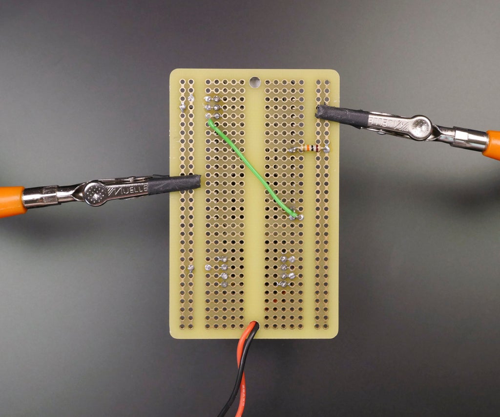
Make up and solder the breadboard wire connections described in the circuit diagram higher up (or to your personal version's specifications), including the 10K puff-up resistor along the sensor's data line.
The star charger's Load pins will provide 3.7V battery power when no solar power exists, but will be powered directly from the star panel if it's plugged in and sunny. Thus the microcontroller must embody able to stick out a diversity of voltages, as low every bit 3.7V and adequate to 6V DC. For those requiring 5V, a PowerBoost (500 or 1000, depending connected the current requisite) nates be used to modulate the Load voltage to 5V (as shown in the Star USB Battery charger project). Here are some common boards and their input voltage ranges:
- NodeMCU ESP8266 (used here): 5V USB operating theater 3.7V-10V Vin
- Arduino Uno: 5V USB Beaver State 7-12V Vin
- Adafruit Huzzah ESP8266 Breakout: 5V USB Beaver State 3.4-6V VBat
In prescribe to accomplish the longest affirmable battery life, you should take whatsoever time to consider and optimize the total current your current draws. The ESP8266 has a cryptic sleep feature which we used in the Arduino sketch to reduce its power consumption dramatically. It wakes up to understand the sensing element and draws more current while it connects to the network to report the sensor's value, past goes back to sleep for a specified amount of time. If your microcontroller draws a lot of power and bottom't easily personify successful to sleep, consider porting your visualise to a well-matched board that draws inferior power. Set down a question in the comments infra if you need help identifying which board could be right-minded for your project.
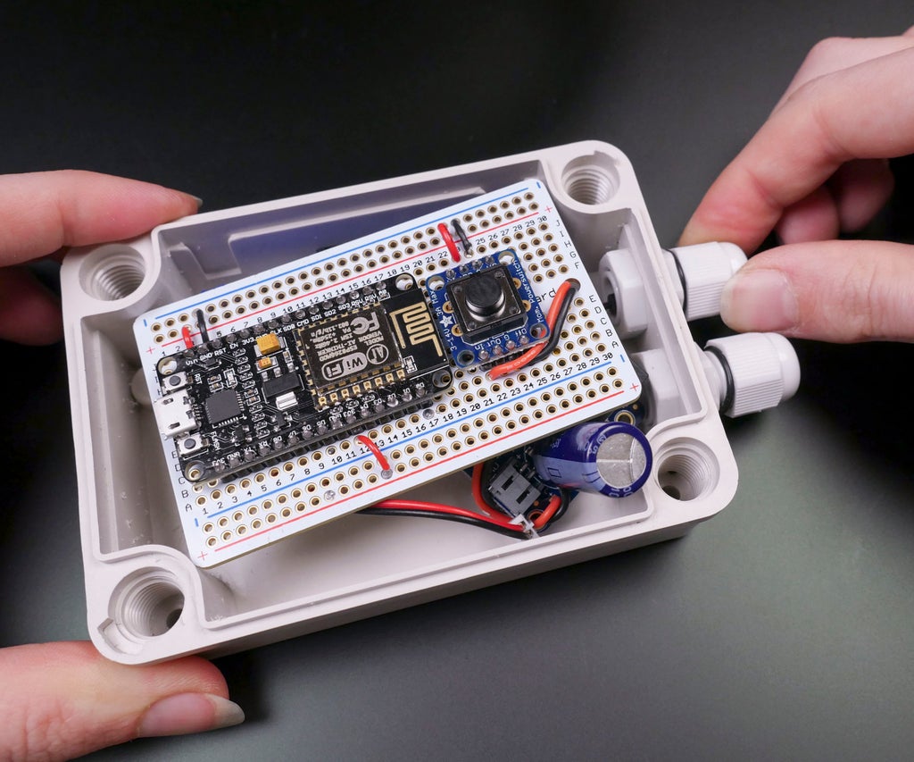
Tone 6: Install Cable Glands

To fix weatherproof entry points for the solar panel cable and sensor cable, we'll install deuce cable glands into the position of the weatherproof enclosure.


Test fit your components to identify the ideal placement, then mark and drill holes in a waterproof enclosure victimization a step drill. Install the two transmission line glands.

Step 7: Complete Tour Assembly
Enter the port side of a waterproof power line into one and solder it to the solar charger's DC stimulant (red to + and bootleg to -).

Insert the soil detector through the early gland, and relate IT busy the perma-proto as per the electrical circuit diagram.

Tape recording the thermistor dig into to the battery. This will limit charging to a safe temperature range spell the project is left unattended outside.

Charging while likewise tasty or overly cold could terms the bombardment or start a fire. Exposure to extreme temperatures can reason damage and castrate the battery's life, so bring it inside if it's below freezing or to a higher place 45℃/113F.
Tighten the cable glands to make a weatherproof varnish around their respective cables.
Tone 8: Prepare Solar array
Accompany my Instructable to splice the cable for your star panel with the plug side of the waterproof DC power line exercise set.
Footstep 9: Screen Information technology
Connect your battery and turn along the electric circuit by pressure the power trade.

Test information technology out and be sure it's reporting to the internet before closing up the enclosure and installing the detector in your herb garden, precious potted plant, or other grease within signal range of your wifi network.

Once the data from the sensor is being logged online, it's easy to put in a formula for email or text alerts on the API gateway site If This So That. I configured mine to e-mail me if the soil moisture plane drops down the stairs 50.
To test it without waiting for my plant to dry prohibited, I manually entered a datum to my humidity feed on Adafruit IO that cut down below the room access. A couple of moments later, the email arrives! If the soil's levels declination infra my nominative horizontal surface, I'll engender an e-mail every time the feed is updated until I water the soil. For my saneness, I updated my computer code to sample the soil a great deal less much than every 15 transactions.
Step 10: Use Information technology Outside!
This is a fun project to customize based happening your plant's hydration needs, and information technology's easy to swap out or add sensors or integrate the solar power features into your new Arduino projects.
Thanks for following along! I'd lovemaking to hear what you reckon; delight post up in the comments. This see is part of my free Solar Class, where you can find easy backyard projects and more lessons on working with solar panels. Verification IT out and enroll!
If you comparable this project, you may be interested in several of my others:
- free Internet of Things Class
- YouTube Subscriber Parry with ESP8266
- Social Stats Tracker Reveal with ESP8266
- Wireless fidelity Weather Display with ESP8266
- Internet Valentine
To keep aweigh with what I'm working on, pursue me on YouTube, Instagram, Twitter, Pinterest, and Snapchat.
Glucinium the First to Share
Recommendations
Source: https://www.instructables.com/Solar-Soil-Moisture-Meter-With-ESP8266/
Posted by: osbywaye1974.blogspot.com
0 Response to "Solar Soil Moisture Meter With ESP8266 : 10 Steps (with Pictures) - osbywaye1974"
Post a Comment